2004 Ford Taurus Car Electrical Diagram Explained
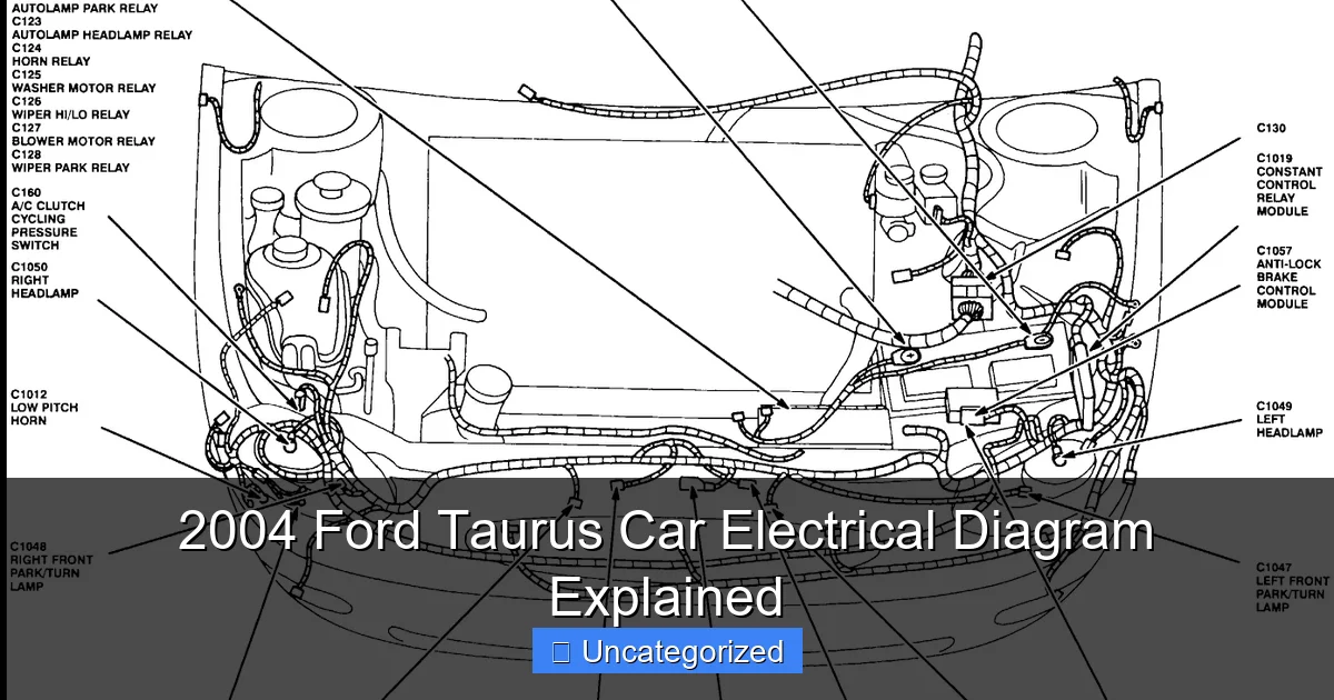
Featured image for 2004 ford taurus car electrical diagram
Image source: justanswer.com
The 2004 Ford Taurus car electrical diagram is a vital tool for diagnosing and repairing complex wiring issues with precision. It provides a detailed, color-coded layout of the entire electrical system, including fuses, relays, sensors, and power distribution. Understanding this diagram empowers DIYers and mechanics to quickly trace circuits, identify faults, and ensure reliable repairs.
Key Takeaways
- Master the main fuse box layout to quickly diagnose power-related issues.
- Identify ground points to troubleshoot electrical failures efficiently.
- Trace wiring color codes for accurate circuit repairs and modifications.
- Locate ECU connections to resolve engine management system faults.
- Review lighting circuits to fix headlight and taillight problems fast.
- Understand relay functions to prevent misdiagnosis of electrical components.
📑 Table of Contents
- Understanding the 2004 Ford Taurus Car Electrical Diagram: A Roadmap to Your Vehicle’s Nervous System
- Decoding the Basics: Components of the 2004 Ford Taurus Electrical System
- How to Read and Use the 2004 Ford Taurus Electrical Diagram Effectively
- Key Circuits and Their Diagrams: A Deep Dive
- Common Electrical Issues and How the Diagram Helps Solve Them
- Maintenance and Upgrades: Leveraging the Diagram for Long-Term Reliability
- Conclusion: Empowering Yourself with Knowledge
Understanding the 2004 Ford Taurus Car Electrical Diagram: A Roadmap to Your Vehicle’s Nervous System
For many car owners, the idea of diving into a 2004 Ford Taurus car electrical diagram might seem like opening Pandora’s box—complex, intimidating, and full of cryptic symbols. Yet, beneath the surface of wires, fuses, relays, and connectors lies a beautifully orchestrated system that powers everything from your headlights to your engine’s ignition. The 2004 Ford Taurus, a reliable midsize sedan known for its comfort and durability, relies heavily on its electrical architecture to function efficiently. Whether you’re a DIY mechanic troubleshooting a faulty power window, a technician diagnosing a persistent check engine light, or a car enthusiast eager to understand how modern automotive electronics work, the electrical diagram is your ultimate guide.
Unlike older vehicles with simple wiring harnesses, the 2004 Taurus integrates a network of modules, sensors, and circuits controlled by the Powertrain Control Module (PCM), Body Control Module (BCM), and other electronic units. This complexity means that a single blown fuse or a corroded ground wire can ripple through multiple systems. That’s why having access to—and understanding—the 2004 Ford Taurus car electrical diagram is not just helpful; it’s essential. This guide will walk you through the core components of the electrical system, decode the diagrams, explain how to use them for troubleshooting, and provide practical tips to keep your Taurus running smoothly. Whether you’re diagnosing a dead battery, replacing a headlight relay, or upgrading your audio system, this post will serve as your comprehensive reference.
Decoding the Basics: Components of the 2004 Ford Taurus Electrical System
Core Electrical Units and Their Roles
The 2004 Ford Taurus electrical system is built around several key components that work in harmony. At the heart of the system are:
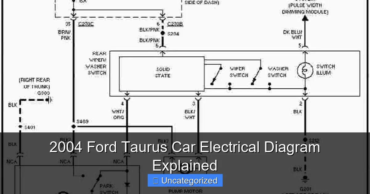
Visual guide about 2004 ford taurus car electrical diagram
Image source: 4.bp.blogspot.com
- Battery and Alternator: The battery provides the initial power to start the engine and supports all electrical loads when the engine is off. The alternator, driven by the serpentine belt, recharges the battery and powers the vehicle once the engine is running. A failure in either can lead to dimming lights, slow cranking, or complete power loss.
- Fuse Boxes (Primary and Secondary): Located under the hood (primary) and inside the cabin near the driver’s side (secondary), these boxes protect circuits from overloads. Each fuse corresponds to a specific system—headlights, wipers, HVAC, etc.—and is labeled in the 2004 Ford Taurus car electrical diagram.
- Relays: Electromagnetic switches that allow low-current circuits to control high-current devices. For example, the headlight relay uses a small signal from the switch to activate the high-power headlight circuit.
- Grounding Points: Critical for completing circuits. Poor grounding can cause erratic behavior in lights, sensors, and even the PCM. The diagram shows grounding points (often marked with a “G” followed by a number) located on the chassis, firewall, and engine block.
- Control Modules: The PCM manages engine functions, while the BCM handles body electronics (doors, lights, wipers, climate control). These modules communicate via the vehicle’s data bus (CAN or J1850 protocol), and their inputs/outputs are detailed in the electrical diagrams.
Understanding Diagram Symbols and Layout
Electrical diagrams use standardized symbols to represent components. In a 2004 Ford Taurus car electrical diagram, you’ll encounter:
- Lines: Represent wires. Color-coded lines (e.g., red, blue, yellow) indicate wire colors. Dashed lines may denote shielded or data wires.
- Fuses and Relays: Illustrated with rectangles containing labels (e.g., “F10” for fuse 10, “R3” for relay 3).
- Connectors: Shown as circles or ovals with numbers (e.g., “C204”) indicating the connector’s location and pin count.
- Switches: Depicted with lines and arrows showing open/closed positions.
- Ground Symbols: A downward-pointing arrow or “G” label marks grounding points.
Example: In the lighting circuit, you might see a red wire (power) from the fuse box to the headlight switch, then a blue wire (output) to the headlight relay, and a black wire (ground) from the headlight housing to G201 on the fender. This layout helps you trace the flow of electricity and identify potential failure points.
How to Read and Use the 2004 Ford Taurus Electrical Diagram Effectively
Step-by-Step Guide to Tracing Circuits
Reading an electrical diagram isn’t about memorizing every wire—it’s about understanding how to follow a circuit. Here’s how to approach it:
- Identify the Circuit: Determine which system you’re troubleshooting (e.g., power windows, HVAC, ignition).
- Locate the Power Source: Start at the battery or fuse box. Find the fuse or relay associated with the system (e.g., “Fuse 12” for power windows).
- Trace the Path: Follow the wire from the fuse to the switch, then to the relay (if present), and finally to the component (e.g., window motor).
- Check Grounds: Every circuit needs a ground. Locate the grounding point (e.g., “G302”) and verify its integrity.
- Look for Control Signals: For systems with modules (e.g., climate control), trace the data lines (e.g., “HS-CAN”) between the switch and the BCM.
Practical Tip: Use a highlighter or colored pen to mark the path on a printed diagram. This visual aid makes it easier to spot breaks or anomalies.
Using Diagrams for Troubleshooting: Real-World Scenarios
Let’s apply this to common issues:
- Headlights Not Working:
- Check the headlight fuse (Fuse 8, 10A) and relay (R4). If the fuse is blown, the diagram helps you identify which circuits are affected (e.g., low beams only).
- Trace the blue/yellow wire from the switch to the relay. Use a multimeter to test continuity.
- Verify the ground at G201. Corrosion here can cause dim or flickering lights.
- Power Windows Unresponsive:
- Check Fuse 12 (30A) in the under-hood fuse box. If blown, inspect the window motor circuit for shorts.
- The diagram shows the master switch sending signals to individual window switches via the LIN bus. A faulty master switch may disrupt all windows.
- Test the ground at G305 (driver’s door frame) for resistance.
- Check Engine Light (CEL) with P0562 (Low Voltage):
- The PCM monitors battery voltage. The diagram reveals the voltage sense wire (red/green) from the alternator to the PCM.
- A loose connection at the alternator or a corroded fuse link can trigger this code.
Tools You’ll Need
- Multimeter: For testing voltage, continuity, and resistance.
- Fuse Puller: To safely remove and inspect fuses.
- Test Light: For quick circuit checks (though less precise than a multimeter).
- Wire Piercing Probes: To test wires without damaging insulation.
- Service Manual: Contains the official 2004 Ford Taurus car electrical diagram and diagnostic procedures.
Key Circuits and Their Diagrams: A Deep Dive
Lighting System (Exterior and Interior)
The lighting circuit is one of the most frequently used and troubleshot systems. The 2004 Ford Taurus car electrical diagram breaks it into:
- Headlights: Powered by Fuse 8 (low beams) and Fuse 9 (high beams). Controlled by the headlight switch and relay. The diagram shows the relay coil (triggered by the switch) and contacts (connecting power to the bulbs).
- Tail Lights and Brake Lights: Fuse 10 powers both. The brake light switch interrupts the circuit when the pedal is pressed. A faulty switch can cause brake lights to stay on or not illuminate.
- Interior Lights (Dome and Map): Fuse 15 supplies power. The diagram includes the door switches and BCM, which control the “dome light delay” feature.
Pro Tip: If only one headlight fails, check the bulb and wiring. If both fail, suspect the relay or switch. The diagram helps you bypass the relay to test if it’s the culprit.
Ignition and Charging System
This system ensures the engine starts and the battery stays charged:
- Ignition Switch: Routes power to the starter solenoid (Fuse 20) and the PCM. The diagram shows the “crank” and “run” positions.
- Alternator: Connected to the battery via a thick red wire. The “L” terminal (exciter) is controlled by the PCM. A faulty exciter wire can prevent charging.
- Starter Motor: Engaged by the starter relay (R5). The diagram reveals the safety interlock (e.g., neutral switch) that must be closed for the starter to work.
HVAC and Climate Control
The 2004 Taurus uses a blend of mechanical and electronic controls:
- Blower Motor: Powered by Fuse 25 (40A). Speed is controlled by the blower switch and resistor pack. The diagram shows the resistor pack’s multiple taps for different speeds.
- AC Compressor: Engaged by the compressor relay (R6) when the AC switch is pressed. The diagram includes the low-pressure switch, which prevents compressor operation if refrigerant is low.
- Temperature Blend Door: Controlled by the BCM based on sensor inputs. The diagram details the feedback circuit from the blend door motor.
Common Electrical Issues and How the Diagram Helps Solve Them
Blown Fuses and Short Circuits
Blown fuses are often symptoms of deeper issues. The 2004 Ford Taurus car electrical diagram helps you:
- Identify Affected Circuits: For example, Fuse 7 (15A) powers the ABS system. If it blows, the diagram shows which sensors (wheel speed, yaw rate) are involved.
- Locate Potential Shorts: Use the diagram to trace wires from the fuse to connectors. A short might occur at a chafed wire near the firewall or a damaged connector.
- Isolate the Problem: Disconnect components one by one (e.g., unplug a headlight) to see if the fuse stops blowing.
Example: A recurring blown fuse for the radio could indicate a short in the aftermarket wiring harness. The diagram helps you identify the factory radio connector (C301) and compare it to the aftermarket setup.
Intermittent Failures and Grounding Problems
Intermittent issues are among the trickiest to diagnose. The diagram is crucial for:
- Pinpointing Grounds: For instance, the BCM is grounded at G303 (driver’s side kick panel). Loose bolts or corrosion here can cause erratic behavior in multiple systems.
- Testing Continuity: Use the diagram to identify test points. For example, if the power mirrors don’t work, test the ground at G304 (mirror housing) with a multimeter.
- Wiggle Test: While monitoring voltage, wiggle wires and connectors shown in the diagram to reveal loose connections.
Module Communication Failures
The PCM and BCM communicate via data lines. The diagram reveals:
- Data Bus Wires: Labeled “HS-CAN” or “MS-CAN,” these wires run between modules. A break or short can disrupt functions like cruise control or door locks.
- Terminating Resistors: Located at the end of the bus, these resistors prevent signal reflection. Their resistance (120 ohms) is specified in the diagram.
- Diagnostic Trouble Codes (DTCs): A code like “U1000” (Network Communication) points to a data bus issue. The diagram helps you test each module’s connection.
Maintenance and Upgrades: Leveraging the Diagram for Long-Term Reliability
Preventive Maintenance Tips
Regular checks using the 2004 Ford Taurus car electrical diagram can prevent failures:
- Inspect Fuses: Replace any that are discolored or corroded. Use the diagram to verify the correct amperage.
- Clean Ground Connections: Remove and clean grounding points (e.g., G201, G302) annually. Apply dielectric grease to prevent corrosion.
- Check Battery Cables: The diagram shows the cable routing. Look for fraying or loose clamps.
- Test Alternator Output: Use the diagram to locate the voltage sense wire and ensure it reads ~14.2V with the engine running.
Upgrading Your Electrical System
The diagram is invaluable for upgrades:
- Adding Aftermarket Accessories: For a subwoofer, use the diagram to find an unused fuse tap or relay. Avoid tapping into critical circuits like ABS.
- Installing LED Lighting: LEDs draw less current. The diagram helps you identify circuits that can handle the load or require load resistors to prevent hyperflashing.
- Upgrading to a Modern Audio System: The diagram shows the factory radio’s pinout (e.g., C301), making it easier to install an aftermarket unit.
Data Table: Common 2004 Ford Taurus Electrical Components and Specifications
| Component | Location | Fuse/Relay | Wire Color | Ground Point | Notes |
|---|---|---|---|---|---|
| Headlights (Low Beam) | Front bumper | Fuse 8 (10A) | Blue/Yellow | G201 (Fender) | Uses relay R4 |
| Power Windows | Doors | Fuse 12 (30A) | Red/Black | G305 (Driver’s door) | Master switch on driver’s door |
| Blower Motor | Under dash | Fuse 25 (40A) | Orange/Black | G302 (Kick panel) | Speed controlled by resistor pack |
| Ignition System | Steering column | Fuse 20 (10A) | Red/Light Green | G303 (Kick panel) | Starter relay R5 |
| ABS Module | Engine bay | Fuse 7 (15A) | White/Blue | G202 (Firewall) | Monitored by PCM |
Conclusion: Empowering Yourself with Knowledge
The 2004 Ford Taurus car electrical diagram is more than a technical document—it’s a roadmap to understanding your vehicle’s inner workings. By mastering its symbols, tracing circuits, and applying the insights from this guide, you can diagnose issues with confidence, perform upgrades safely, and extend the life of your Taurus. Whether you’re replacing a fuse, troubleshooting a mysterious electrical glitch, or installing a new stereo, the diagram turns complexity into clarity. Remember, every wire, relay, and ground point has a purpose, and the diagram reveals their relationships. Keep a copy in your glove compartment, bookmark it on your phone, or print it for your garage. With this knowledge, you’re not just a car owner—you’re a skilled technician, capable of keeping your 2004 Ford Taurus running smoothly for years to come. After all, in the world of automotive repair, knowledge isn’t just power—it’s the spark that keeps everything running.
Frequently Asked Questions
Where can I find a reliable 2004 Ford Taurus car electrical diagram?
You can find a detailed 2004 Ford Taurus car electrical diagram in the official Ford service manual, Haynes repair guides, or trusted online automotive databases like AutoZone or Mitchell1. These sources provide accurate schematics for troubleshooting and repairs.
How do I read the 2004 Ford Taurus electrical diagram for fuse box issues?
The diagram labels each fuse and relay with a number, amperage, and corresponding circuit (e.g., “F25 – 10A – Radio”). Match the fuse number to your owner’s manual to identify the affected component and check for blown fuses or shorts.
What do the color codes mean in the 2004 Ford Taurus car electrical diagram?
Wire colors in the diagram (e.g., BK/YL for black/yellow) indicate insulation colors and tracer stripes, helping you trace circuits. Refer to the legend in the manual for exact color abbreviations and their functions in the system.
How can I use the electrical diagram to diagnose a non-working power window in my 2004 Taurus?
Check the 2004 Ford Taurus car electrical diagram to locate the power window circuit, including switches, fuses, and motors. Test for voltage at the switch and motor connections using a multimeter to isolate the fault.
Does the 2004 Ford Taurus electrical diagram include the ignition system?
Yes, the diagram covers the ignition system, including the coil, starter relay, and ignition switch. It maps the power flow from the battery to the spark plugs, aiding in diagnosing no-start or misfire issues.
Can I find a free PDF version of the 2004 Ford Taurus car electrical diagram?
Free versions may be available on forums like Taurus Car Club or Ford enthusiast sites, but quality varies. For guaranteed accuracy, purchase a factory manual or use a subscription-based service like AlldataDIY.